OK so now that we can tell openSCAD to make basic shapes we now want to be able to move them around, rotate them and while we are at it any other transformations we can throw in at the same time.
So lets start with a basic cylinder
cylinder(h=10,r=5,$fn=30);
now as you can see we have made a cylinder with its base centred at the origin, and extending in the positive z direction. So in order to move the cylinder around we use the translate command, lets start by moving the cylinder 5 units along the x direction
translate([5,0,0])

{

  cylinder(h=10,r=5,$fn=30);

}
Things to note here are firstly that the translate command is not followed by a semicolon, and secondly that we have placed curly braces around the object that has been moved. For the translate command everything that is placed within the curly braces will be moved, so if you have two objects that you wish to move you can place them both inside the braces to move them together.
Now there is another way of using the translate command, but personally i find i preffer to stick with the method abouve. If you would rather however you can get the same effect by running the following command
translate([5,0,0])cylinder(h=10,r=5,$fn=30);
This method moves only the object on the same line as the translate([5,0,0]) command, and again we don’t put a semicolon after the translate command.
Now next up is rotation, unfortunately this can become a little more complicated, as not only can you an object around the x,y and z axis, we can also rotate them around an arbitrary axis as well. To begin with we will start simple, to make things easier to see lets start with an odd shape so that we can clearly see when it has been rotated
cylinder(h=10,r1=5,r2=2,$fn=3);
As with the translate command can define tell an object to rotate either using the curly braces or without, but i will stick to using them as i think it helps make the code easier to read. Lets start by rotating objects around the x,y and z axis by 45′ around each axis
rotate(a=[45,45,45])

{

  cylinder(h=10,r1=5,r2=2,$fn=3);

}

Object rotated around the x y and z axis
In this instance the a= is optional, but it will be helpfull when reading through your code especially when rotating objects around other more complicated axes than the x,y, and z. On that point lets say rather than rotating your object around the x,y and z axis, you want to rotate an object around an axis that is half way between the x and y axis, but still in the x-y plane,
rotate(a=45,v=[1,1,0])

{

  cylinder(h=10,r1=5,r2=2,$fn=3);

}
here the v=[1,1,0] section defines a line around which to rotate that points in from the origin to the point x=1, y=1, z=0. Bare in mind that you will rotate around this axis, not towards/away from this axis. Again the v= part is optional but will help you read you code (in my opinion).
OK so now we have move and rotate the same object, now the order in which we do things is now important
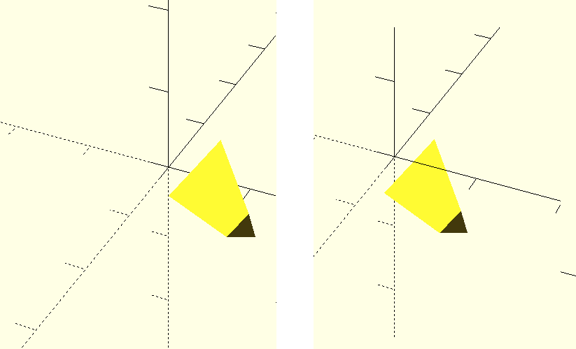
left rotate then translate, right translate then rotate
Both of these objects have been translated by 5 units and rotated 45 degrees around [1,1,0], but you can see they have ended up in different positions. This is because the rotate command rotates things around the axis defined by the line from the origin to the [1,1,0] point. so if you rotate an object that has already been moved things can end up doing strange things. This isn’t to say never do things in this order, but just be aware of this. The code for the two translations are
for the left image:
translate([5,0,0])

{

  rotate(a=45,v=[1,1,0])

  {

    cylinder(h=10,r1=5,r2=2,$fn=3);

  }

}
for the right image:
rotate(a=45,v=[1,1,0])

{

  translate([5,0,0])

  {

    cylinder(h=10,r1=5,r2=2,$fn=3);

  }

}
Note that the brackets are completed from the inside out. For day to day use these should be the only transformations you will need, however there are a few others that you can use.
First of these is the scale transformation scale([x,y,z]){...}. This command takes the object in the curly braces and scales by x,y,and z along those dimensions. for example if you have a cube with a corner at 1,1,1 and use scale([0.5,1,1.5]){...}, this corner will be moved to 0.5,1,1.5. For this reason it is important again in which order you apply these transformations.
Next up is a similar command resize([x,y,z]){...} but rather than scaling the object by factors x,y and z now we simply say what the final size of the object should be.
The final transformation I will talk about is mirror([x,y,z]){...} which sounds like it should be simple to explain and in principle it is but the details get complicated. The command mirrors the about a plain that you define. The complicated part for some people may be in how the plane is defined, with [x,y,z] defining a normal vector to the plane, for people who have studied maths or physics this will be enough detail but for those who dont know what a normal vector is, let me try and explain. A simple way of explaining how to think of how to define this plane would be to draw a line from the origin to [x,y,z], and imagine looking back from the point towards the origin and drawing a circle with the origin at the centre, this circle will be in the mirror plane.